Model of repeated attribute that avoids NULLs and adapts easily
Introduction
The contacts example introducing subkeys is also an excellent illustration of another problem that is found in many database designs: repeated attributes.
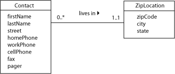
Obviously, the contacts database will need to store phone numbers in addition to addresses. The figure below depicts a typical simplistic model of such information, with the correction to the zip code subkey problem.

This might seem like a reasonable design until you look at the information that could be inserted in the database as illustrated in the table below. We are omitting the street and zip to reduce table width and to focus our attention on the phone number values.
| George | Barnes | 562-874-1234 | 310-999-3628 | |||
| Susan | Noble | 562-975-3388 | 714-847-3366 | |||
| Erwin | Star | 714-997-5885 | 714-997-2428 | |||
| Alice | Buck | 562-577-1200 | 562-561-1921 | |||
| Frank | Borders | 714-968-8201 | ||||
| Hanna | Diedrich | 562-786-7727 |
Problems with Repeated Attributes
There are at least two very significant problems with the model, as illustrated with by the contents in the table above. Note that while we present rows of a typical table, such instances are problematic and as database developers, we should never create them. Before creating tables and inserting rows, we need to ensure the database has been well-designed.
- None of our contacts are going to have all of the phone numbers that we've modeled for. In fact, most contacts will have only one or two numbers—leaving most of these fields blank, or NULL. Remember that NULL is a special constant value in database systems that represents the absence of a value; that is “this field doesn’t have any value assigned to it.” It’s not the same as a zero length string or the number zero. In general, we want to eliminate unnecessary NULLs that might occur as a result of our design—and the NULLs in this table are definitely unnecessary.
- No matter how many phone number fields we provide (five of them here), sooner or later someone will think of another kind of phone number that we need. In fact, can you think of a kind of phone number that does not fall in one of the types illustrated above? With the model above, we would have to actually change the table structure to add another field. Such structural changes to a table can be expensive and would increase the number of NULLs as none of the previously inserted rows would have a value for the new type of phone number.
Information that might change should be represented by data in a table rather than by the table structure; thus, it needs to be represented by an attribute in the model. As the model and data above show, the problem is that the column name itself encodes information about the values in said column. Above, each column represents a phone number but the column name is what encodes the type of phone number the column represents. This is a problem; we solve it by modeling such information in an attribute, as the next section shows.
The Repeated Attribute and a correct model
In fact, we don’t have five single attributes here, one for each type of phone. We have one repeated attribute, phone, that also has an attribute of its own that tells us what type of number it is (home, work, cell, and so on). In effect, it’s a class within a class. Some database textbooks call this structure a weak entity, since it cannot exist without the parent entity type.
In UML, we can show multiplicity of attributes the same way we show multiplicity of an association (for example [0..*]). We can also show the data type of an attribute, which in this case is a structure (PhoneNumber). We have listed the structure attributes below in parentheses; however, that is not valid UML syntax and is provided here only for completion.

Mapping to the Relational Model
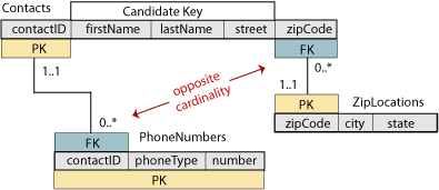
If we try to represent information this way in the Contacts table, we’ll end up with a subkey that, as discussed previously in the Subkeys design pattern, is not desirable as it leads to redundancy. We have to create a new table in much the same way as was done for the zip code locations. Below is the list of steps that will achieve the correct mapping.
- Remove all of the phone number fields from the Contacts relation. Create a new scheme that has the attributes of the PhoneNumber structure (phoneType and number).
- The Contacts relation has now become a parent, so we should add a surrogate key, contactID. Copy this into the new scheme, so that we can associate the phone number with the person it belongs to. There is now a one-to-many relationship between Contacts and PhoneNumbers. Notice that this is the opposite of the relationship between Contacts and ZipLocations.
- To identify each phone number, we need to know at least who it belongs to and what type it is. However, to allow for any combination of contacts, phone types, and numbers, we will use all three attributes of the new scheme together as the primary key—it’s not a parent, so we are not concerned about size of the PK. Notice the high amount of flexibility we gain as now a contact can have any number of cell phones, and similarly for any of the other types of phones. Furthermore, if a new phone technology comes along, a phone number of this new type can easily be inserted in the database without changing the structure of any of the tables.

The Contacts table now looks like it did before we added the phone numbers (with the addition of the contactID). The new PhoneNumbers table can be joined to the Contacts on matching contactID pk-fk pairs to provide all of the information that we had before.
| 1639 | George | Barnes | 1254 Bellflower | 90840 |
| 5629 | Susan | Noble | 1515 Palo Verde | 90840 |
| 3388 | Erwin | Star | 17022 Brookhurst | 92708 |
| 5772 | Alice | Buck | 3884 Atherton | 90836 |
| 1911 | Frank | Borders | 10200 Slater | 92708 |
| 4848 | Hanna | Diedrich | 1699 Studebaker | 90840 |
| 1639 | Home | 562-874-1234 |
| 1639 | Cell | 310-999-3628 |
| 5629 | Home | 562-975-3388 |
| 5629 | Work | 714-847-3366 |
| 3388 | Fax | 714-997-5885 |
| 3388 | Pager | 714-997-2428 |
| 5772 | Work | 562-577-1200 |
| 5772 | Cell | 562-561-1921 |
| 1911 | Home | 714-968-8201 |
| 4848 | Cell | 562-786-7727 |
Case study: employee dependents
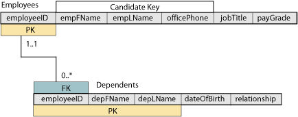
The modeling technique shown above is useful where the parent class has relatively few attributes and the repeated attribute has only one or a very few attributes of its own. However, you can also model the repeated attribute as a separate class in the UML diagram. One classic textbook example is an employee database. The employee class represents “a person who works for our company”; each employee has zero or more dependents for whom information needs to be maintained for insurance purposes. The dependent is conceptually a repeated attribute of the employee, but can be described separately as “a person who is related to the employee and may receive health care or other benefits based on this relationship.” We can represent this fact as an additional UML class in the diagram, as shown in the figure below.

The relation scheme is a standard one-to-many; the PK of the many-side relation will have to include the FK from the parent since it is a weak entity type. In addition to the FK, the PK will also include one or more local attributes to guarantee uniqueness. The relational database scheme diagram is given below.

